When you walk into a hotel, lighting shapes your first impression before you even notice the décor. The right hotel lighting welcomes you, sets the mood, and makes you feel at ease. Sunwin Lighting stands out by offering solutions that match your style and meet your guests’ needs, creating spaces that leave a lasting impact.
Lighting Impact on Guest Experience

First Impressions Matter
When you step into a hotel lobby, the lighting greets you before anyone else does. The way a space glows can shape your first impression in seconds. You might notice how the light makes the room feel welcoming or how it highlights the elegant details of a luxury hotel. Good lighting choices help you relax and feel comfortable right away.
Take a look at how different aspects of lighting affect your experience:
|
Evidence Type
|
Findings
|
|
Visual Comfort
|
Lighting significantly impacts visual comfort, which is crucial for guests' first impressions. High illuminance reduces fatigue and anxiety.
|
|
Color Temperature
|
Warmer light creates a more positive atmosphere, enhancing guests' feelings of security and relaxation.
|
|
Overall Atmosphere
|
The combination of lighting, color, and decoration style shapes the lobby's atmosphere, influencing guest satisfaction and perceptions.
|
You want to feel safe and at ease when you arrive. Lighting for hotels plays a big role in that. A bright, well-lit entrance makes you feel secure. Warm tones can make you feel relaxed, while cooler lights might energize you. Here are some ways lighting design in hotel entrances can influence your decisions:
-
You feel welcome and secure when the lighting is right.
-
Positive experiences boost your opinion of the hotel brand and can make you want to book again.
-
Natural light makes spaces feel more inviting.
-
Rooms without daylight seem unwelcoming, which can lower your interest in booking.
-
A welcoming atmosphere increases guest satisfaction.
-
Positive first impressions often lead to higher booking rates.
-
When you feel secure because of effective lighting, you are more likely to return.
-
Good visibility adds to a positive guest experience.
Sunwin Lighting understands how important these first moments are. Our hotel lighting programs use modern fixtures and thoughtful designs to create spaces that impress guests from the moment they walk in. You get both style and comfort, making your stay memorable.
Setting the Mood
Lighting does more than just help you see. It sets the mood and creates the ambiance you remember long after you leave. When you walk into a hotel, the lighting can make the space feel cozy, vibrant, or even luxurious. The right lighting choices are key to impacting mood and shaping your overall guest experience.
Here’s how lighting helps set the mood:
-
Lighting establishes the mood and atmosphere of a space, shaping the overall vibe.
-
Customizable LED lighting solutions let hotels create different moods for special occasions, enhancing guest experiences.
-
Lighting can evoke emotions, making spaces feel serene, calming, energetic, or lively.
-
The interplay of light and shadow is essential for crafting the desired ambiance.
-
Lighting creates a warm and inviting atmosphere for guests as soon as they step into the lobby.
-
Good lighting enhances the appearance of colors and designs, showing off the beauty of the hotel’s décor.
-
Hospitality lighting experts know how to use light to create emotional connections with guests.
Color temperature also plays a big part in how you feel. Warm lights create a calming environment, perfect for relaxing after a long day. Cooler lights help you stay alert and focused, which is great for workspaces or active areas. When hotels use the right color temperatures, you feel more positive and comfortable, which can lead to repeat bookings and stronger brand loyalty.
Sunwin Lighting specializes in creating these memorable experiences. Our wide range of products, from LED mirrors to stylish table lamps and ceiling lights, gives you the flexibility to design spaces that match your brand and meet your guests’ needs. We focus on quality and innovation, so you get durable fixtures with modern features like USB charging and power outlets. With Sunwin Lighting, you can transform any hotel space into a place guests love to return to.
Psychological Effects of Hotel Lighting

Mood and Well-Being
Have you ever noticed how your mood changes when you walk into a hotel room with soft, warm lighting? You instantly feel more relaxed and at ease. Lighting does more than just brighten a space. It shapes how you feel and how well you rest. Studies show that when you can control the lighting in your room, like using dimmable lights, you feel less moody and more comfortable. Bright, cool-white light works best during the day in busy areas, while warm lighting helps you unwind in the evening.
Research also points out that sustainable lighting in hotels, especially in beach resorts, boosts your mood and helps you relax. You sleep better and feel less stressed when the lighting creates a cozy atmosphere. Adjustable LED systems let you set the ambiance you want, making your stay more enjoyable. Warm light even helps your body produce melatonin, which means you fall asleep faster and wake up refreshed. Cooler lights keep you alert when you need to focus.
Sunwin Lighting understands how important mood and well-being are for guests. You get access to advanced lighting solutions that let you personalize your space. Our products help you create the perfect ambiance, whether you want to relax after a long day or stay energized for work. With Sunwin Lighting, you can count on a hotel lighting program that supports your comfort and happiness.
Comfort and Safety
You want to feel safe and comfortable every time you walk through a hotel corridor or settle into your room. Lighting plays a huge role in making that happen. Proper lighting improves visibility, which is key for safety in hallways and guest rooms. Soft, ambient lighting gives you a sense of luxury and comfort, making you feel like you’re in a luxury hotel. Well-lit spaces also look cleaner and more spacious, so you feel more at ease.
Here’s how lighting design helps you feel safe and comfortable:
-
Proper lighting enhances visibility, which is crucial for safety in corridors and guest rooms.
-
Soft, ambient lighting is associated with luxury and comfort, improving guests' perceptions of the space.
-
Well-lit areas contribute to a sense of cleanliness and spaciousness, making guests feel more at ease.
-
Emergency lighting and illuminated pathways guide guests safely during emergencies, reducing panic.
You’ll notice that different areas in a hotel need different lighting strategies. Lobbies use warm, inviting lighting to encourage you to linger, while corridors rely on brighter lights for safe navigation. Accent lighting highlights beautiful design features, adding to the overall ambiance. Warm lighting in guest rooms creates a comforting atmosphere, while brighter lighting in corridors ensures you can move around safely.
Sunwin Lighting excels at creating safe and comfortable environments for guests. Our hotel lighting solutions include emergency lighting, ambient fixtures, and accent lights that work together to make every space feel secure and welcoming. You get high-quality products designed for durability and modern convenience, so you always feel at home.
Key Hotel Lighting Elements

Color and Ambiance
You notice the mood of a space as soon as you walk in. Color temperature plays a big role in shaping that feeling. In hotel lobbies, a warm color temperature between 2700K and 3000K creates a cozy, intimate atmosphere. Bedside lamps in guest rooms often use warmer light for comfort, while desk lamps might be a bit brighter to help you focus. Restaurants feel more inviting with warm lighting, and banquet halls can switch between warm and bright depending on the event.
-
Lobby Lighting: 2700K–3000K for warmth and intimacy
-
Guest Room Lamps: 3000K for comfort, 4000K for focus
-
Restaurant Lighting: 2700K–3000K for a pleasant dining experience
-
Banquet Halls: Warm for weddings, bright for business events
The colors in a hotel environment also affect how you feel. Warm colors like red and orange make spaces lively and welcoming. Cool colors such as blue and green help you relax. Warm lighting adds comfort, while cool lighting brings calmness and a sense of luxury hotel style.
Brightness and Control
You want to control your environment. Adjustable lighting lets you set the brightness to match your mood or activity. This flexibility improves your comfort, sleep, and productivity. Hotels that use the right color temperature and give you control over brightness see fewer complaints and better guest feedback. You can tailor the lighting to your needs without changing the whole room.
Modern features like USB charging ports and power outlets in lamps make your stay even easier. You can charge your devices right at your bedside or desk. Sunwin Lighting offers these smart solutions, making your experience more convenient and enjoyable.
Layered Lighting
Layered lighting means using different types of lights together. You get ambient lighting for general brightness, task lighting for activities like reading, and accent lighting to highlight special features. This approach creates depth and makes each space feel unique.
-
Ambient Lighting: Sets the base mood with ceiling lights or chandeliers
-
Task Lighting: Focused light for reading or working, like LED mirrors or table lamps
-
Accent Lighting: Highlights artwork or architectural details
Most guests prefer a mix of ceiling lights and table lamps. This combination lets you adjust the ambiance for any activity. Sunwin Lighting’s range—including LED mirrors, wall lamps, and floor lamps—helps you create the perfect layered effect. Our products stand out for their quality, durability, and modern features, making your hotel lighting both beautiful and functional.
Personalization in Guest Room Lighting
Customizing for Preferences
You want your hotel room to feel like your own space. Personalization in hotel lighting lets you adjust the ambiance to match your mood or activity. Many hotels now use smart systems that allow you to control brightness, color, and even the direction of light. You can set warm lights for a cozy evening or switch to bright, cool lights when you need to focus.
Studies show that mood lighting can make guests happier by up to 58%. When you have control over your lighting, you feel more comfortable and satisfied. Here’s a quick look at how personalized lighting impacts your guest experience:
|
Evidence Type
|
Description
|
|
Mood Lighting Impact
|
Guests report higher happiness with adjustable lighting.
|
|
Personalized Control
|
Smart systems let you change lights for different activities.
|
|
Immersive Environments
|
Tunable white control helps you focus or relax with different colors.
|
Hotels use different lighting strategies to meet your needs. You might find presence sensors in your room, like at The Sinclair hotel, which let you adjust lighting levels with a simple touch. Only 23% of guests say they get high levels of personalization, so there’s room for improvement. Sunwin Lighting stands out by offering advanced solutions that help hotels create a tailored experience for every guest. Our products let you control your environment easily, making your stay more enjoyable.
Special Occasions
You want your stay to feel special, especially during important moments like honeymoons or anniversaries. Hotels create memorable experiences by customizing lighting for these occasions. Imagine walking into a room with soft, romantic lighting and beautiful accents. The Grand Hotel on Mackinac Island offers a Grand Romance package with a private sunset candlelit dinner. Ledges Hotel features a Romance by the Falls package, complete with flowers and sparkling wine.
Hotels use accent lighting to highlight flowers or special décor. Ambient lighting sets the mood for celebration. Functional lighting lets you adjust brightness for a cozy dinner or a relaxing evening. Sunwin Lighting helps hotels deliver these experiences with versatile products that support every lighting strategy. You get the perfect ambiance for your special day, making memories that last.
|
Metric
|
Description
|
|
Guest satisfaction scores
|
Surveys assess comfort, mood, and style after stays.
|
|
Repeat booking rates
|
Hotels track if improved lighting leads to more returns.
|
|
Social media engagement
|
Guests share photos and comments about lighting and design.
|
Real-World Hotel Lighting Success

Boutique Hotel Case
Imagine you walk into a boutique hotel where every detail feels intentional. Sunwin Lighting worked with a downtown boutique to upgrade their guest rooms and lobby. The team installed high CRI LEDs, which made colors pop and artwork stand out. You notice the layered lighting approach right away. Ambient ceiling lights set a relaxing tone, while accent lamps highlight unique décor. Guests rave about the cozy atmosphere and the ability to adjust brightness for reading or relaxing. The hotel saw a boost in guest satisfaction scores and more positive reviews online.
Resort Transformation
You might wonder how lighting can change the vibe of a resort. Sunwin Lighting partnered with a coastal resort to revamp their lighting program. The results speak for themselves:
-
Creates a warm, inviting ambiance that welcomes you from the moment you arrive
-
Achieves up to 80% energy savings, helping the resort invest in other guest amenities
-
Reduces maintenance calls because LEDs last longer
-
Enhances appeal to eco-conscious travelers who value sustainability
The resort now attracts more guests who care about the environment. You feel comfortable knowing the hotel lighting supports both style and sustainability.
Best Practices
If you manage or design hotel spaces, you want to learn from successful projects. Here are some best practices from Sunwin Lighting’s real-world experiences:
-
Use high CRI LEDs for true color representation
-
Implement layered lighting to create depth and ambiance
-
Focus on energy efficiency to lower costs
Hotel managers and designers also share important lessons:
-
Balancing aesthetics with environmental responsibility matters for facade lighting
-
Address maintenance challenges early to avoid disruptions
-
Consider budget and ROI before upgrading systems
-
Choose sustainable, eco-friendly lighting solutions
-
Integrate smart technologies for efficient control
You may face challenges when upgrading lighting systems. Here’s how hotels overcome them:
|
Challenge
|
Solution
|
|
Initial costs
|
Conduct thorough cost-benefit analyses
|
|
Technological adaptation
|
Provide continuous education and training
|
|
Compatibility issues
|
Select the right technology partners
|
When you choose Sunwin Lighting, you get a partner who understands your needs and delivers solutions that elevate guest experiences.
You see how lighting shapes every hotel stay. When you use innovative lighting, you boost guest satisfaction and loyalty. Look at what others have done:
Sunwin Lighting helps you stand out with custom-made, high-quality products like LED mirrors and table lamps. Our focus on technology and sustainability means you can create unique, memorable spaces for every guest.
FAQ
How does hotel lighting affect your stay?
Lighting shapes your mood and comfort. You feel more relaxed in warm, inviting spaces. Good lighting helps you sleep better and enjoy your room. Hotels use lighting to create memorable experiences for every guest.
Can you control the lighting in your hotel room?
Many hotels offer adjustable lighting. You can change brightness or color to match your mood. Some rooms have smart controls or dimmable lamps. Sunwin Lighting provides modern fixtures that make it easy for you to personalize your space.
What types of lighting fixtures do hotels use?
Hotels use a mix of ceiling lights, table lamps, wall lamps, and LED mirrors. Each fixture serves a purpose. You get ambient light for general comfort, task lighting for reading, and accent lights for style.
Why should hotels choose Sunwin Lighting?
You get high-quality, durable products with modern features like USB charging and power outlets. Sunwin Lighting offers a wide range of stylish options. Our team helps hotels create unique, comfortable spaces that guests love.
Does lighting impact hotel safety?
Yes! Proper lighting keeps hallways and rooms safe. You see clearly and avoid accidents. Emergency lights guide you during unexpected events. Hotels rely on well-designed lighting to protect guests and staff.


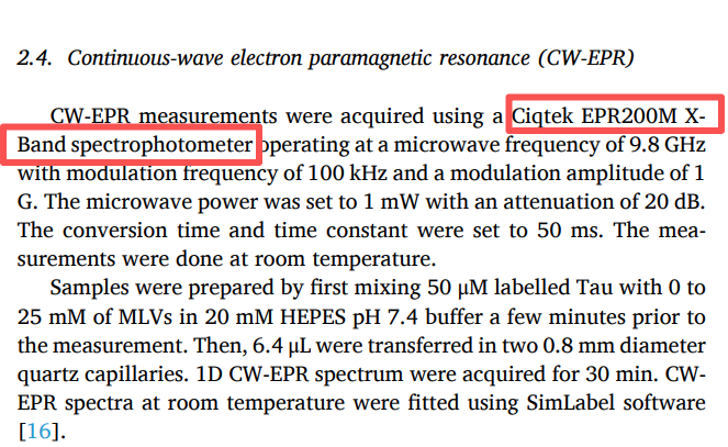
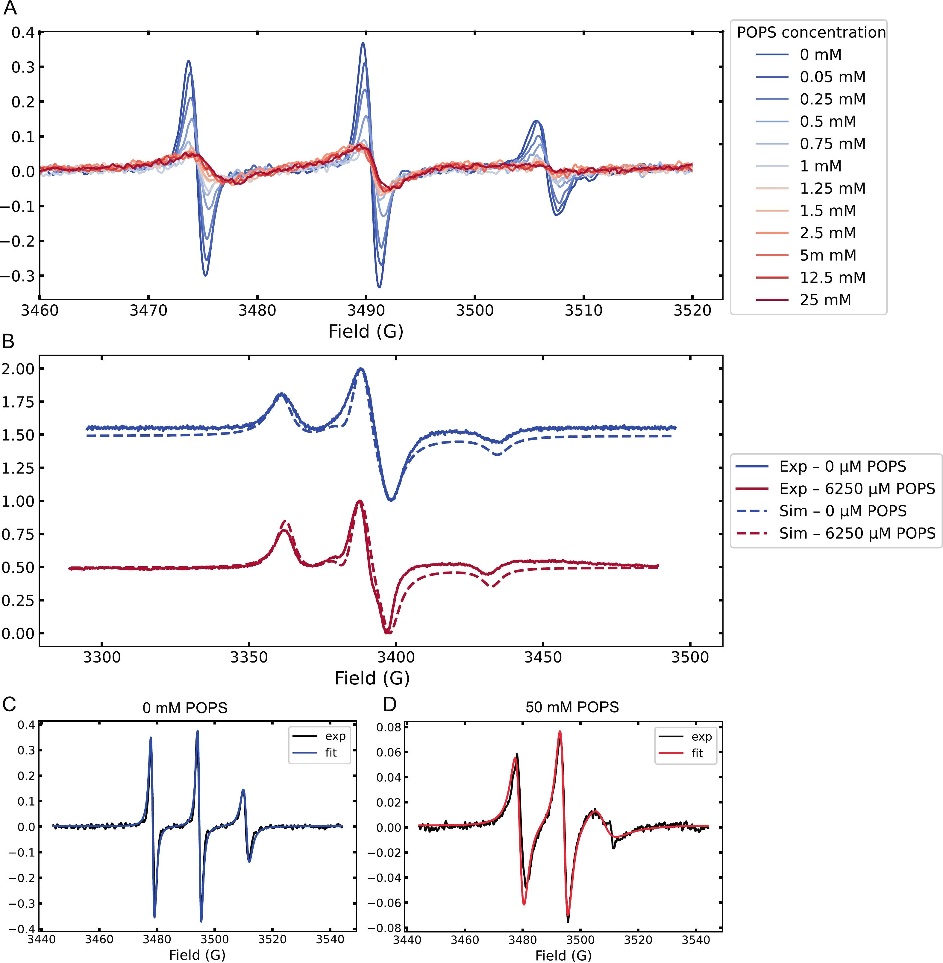 Figure 1. (A) Room-temperature CW-EPR spectra of spin-labeled Tau during titration with increasing concentrations of POPS MLVs, showing gradual line-shape changes.